In any process industry or a power plant efficiency is an important factor that needs to be considered. And are aimed to increase the efficiency
Feeding water directly to the boiler drum without preheating requires more fuel to generate the steam. This is not so efficient.
In this article, we will discuss how the boiler efficiency is increased by its auxiliaries
What is Boiler as per IBR?
As per the Indian Boiler Regulation (IBR) act the boiler is any closed vessel exceeding a capacity of 22.7 liters used to generate steam under pressure with necessary mountings installed to it.
What is efficiency in the boiler?
The boiler efficiency is defined as the ratio of the main steam output to the fuel required for the boiler.
Why does the efficiency of the boiler need to be maintained?
To drive the steam turbine the main steam of high pressure and high temperature is required. That makes the boiler design more complex
For an efficient boiler, generating the steam of 1 ton requires 0.55 tons of fuel (Ex: Bagasse)
What are the boiler auxiliaries?How do they help in increasing the boiler efficiency?
The boiler auxiliaries are an integral part of an industrial boiler but are not mounted on it. The main purpose of the boiler auxiliaries is to preheat a fluid to reduce energy consumption. The feed water is passed through various stages of the boiler called boiler auxiliaries to pre-heat the boiler feedwater, to increase the efficiency thereby reducing the required fuel for combustion. The boiler auxiliaries are
Deaerator:
A Deaerator is an integral part of the boiler, the function of the deaerator is to remove the dissolved oxygen and other non-condensable gases from the feed water.
Deaerator
The dissolved oxygen present in the boiler feedwater causes damage to water tubes by sticking to the walls of metal pipes and other metallic equipment, In most boiler systems the deaerators are installed to remove oxygen down to levels of 7 parts per billion by weight (0.005 cm³/L). The feed water in the deaerator is sprayed in the steam area where it is heated close to its saturation temperature of steam with a minimum pressure drop. In the tray section of the deaerator, the water moves from tray to tray into fine droplets getting in contact with incoming steam. The feed water temperature at the deaerator outlet is 110 degrees Celsius.
Boiler feed pump:
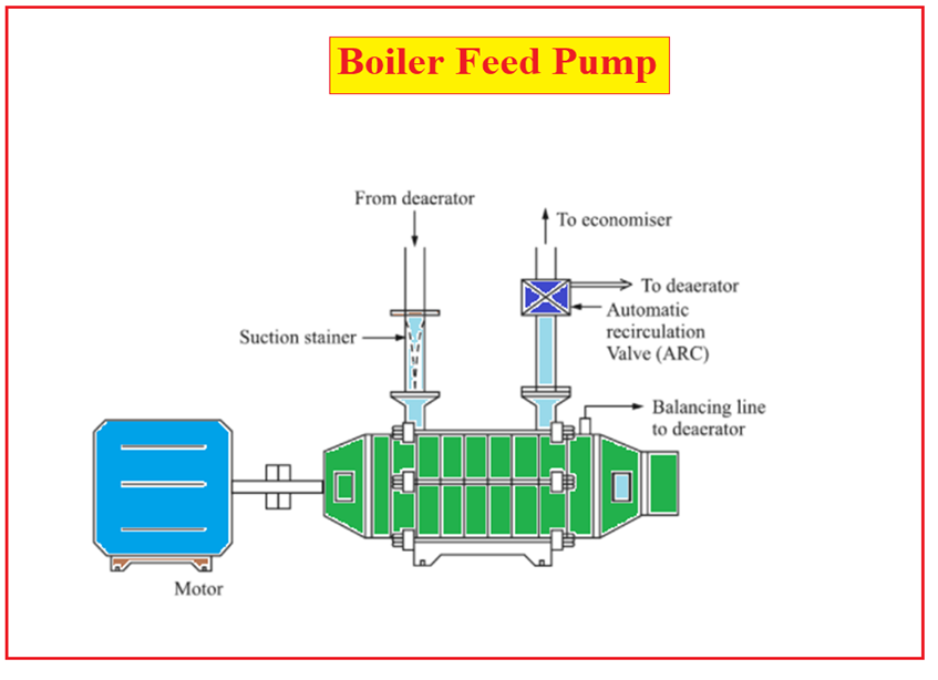
The pumps are generally multistage centrifugal type and reciprocating pumps driven by an electric motor. The high-pressure boiler feed pump transfers feed water from the deaerator to the economizer through HP heaters, the pressure of the feed pump is so chosen that the water shall enter to drum against the drum pressure. The main objective of the feedwater control station is to balance the main steam flow and feedwater flow in proportion to maintain a safe water level in the steam drum at any boiler load condition.
Boiler feed pump
The steam flow in TPH must be equal to the feedwater flow in TPH. Steam Flow = Feedwater Flow If the boiler operating pressure is 110 Kg/cm2 then the feed water pressure must be 135 to 140 Kg/cm2 (i.e. 15% to 20% higher ). Main Steam Pressure < Drum Pressure < Feedwater Pressure
High Pressure (H.P) Heaters:
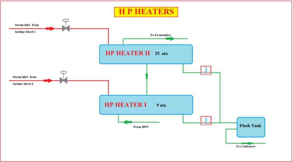
H P Heater
The boiler feedwater from the deaerator enters the H.P heater I of 9 ata, and H.P heater II of 25 ata, through the feed pump. The boiler feed water in HP heaters is pre-heated using the steam from the turbines bleeds I and II. The steam from turbine bleed I enter the H.P heater II and the steam from turbine bleed II enters the H.P heater I. The feedwater temperature at the H.P heater I outlet is 150 degrees Celsius. The feedwater temperature at the H.P heater II outlet is 210 degrees Celsius. Economizer: It is a heat exchanger device, in which the boiler feedwater is preheated by utilizing the waste heat of the exhaust flue gas before venting into the atmosphere through the chimney, The feed water from the High-Pressure heaters enters the economizer and picks up heat from the waste flue gases from the superheater. The flue gas temperature in the economizer inlet and outlet is about 480 and 320 Degrees Celsius. The feed water temperature at the economizer outlet is 300 degrees Celsius.
Economizer
Super Heater:
Super Heater
A Superheater is an integral part of the boiler and is placed in the path of hot flue gases from the furnace. A superheater is a device that converts wet steam into dry super-heated steam. The heat recovered from the High-Temperature flue gases at the furnace is used to superheat the steam the furnace temperature is maintained up to 950 Degrees Celsius
The purpose of a superheater is to increase the temperature of saturated steam maintaining constant pressure.
De-Super heater:
To obtain accurate control of the degree of superheated steam de-super-heater is required. This is a device installed between the stages of the superheater that sprays water into the superheated steam to maintain its temperature.
It is also known as Attemperator.
Air Preheater:
It is a device in which the waste heat of the flue gas is utilized for preheating the air supplied for the combustion of the fuel in the furnace to increase the boiler efficiency by reducing the heat loss in the flue gas.
The flue gas temperature in the air preheater is about 270 Degrees Celsius
Mechanical draught systems:
Forced Draught (F.D) Fan:
A forced Draught (F.D) Fan is used to supply combustion air to the boiler furnace. The air supplied through this F D Fan allows the fuel to burn fully ensuring complete combustion; by this, the efficiency can also be achieved by these draught systems.
Secondary Air (S.A) Fan:
After dropping the fuel (bagasse) from the screw feeder the secondary air fan at the boiler furnace increases the airflow to make proper combustion allowing the fuel to burn properly in the furnace chamber providing sufficient air for achieving the boiler efficiency to save the fuel.
Mechanical draught systems
Induced Draft (I.D) Fan:
It is placed at the flue gas path between Electrostatic Precipitator & Chimney. This fan takes out the combustion product (hot flue gas with dust particles) from the furnace and exits it into the atmosphere.
The heat of flue gas is passed through different heat transfer elements. After passing through all elements the flue gas temperature reduces because this heat is utilized to preheat the feed water.
Chemical dosing:
The boiler is equipped with two chemical dosing systems, one for Low-Pressure dosing and the other for High-Pressure dosing.
The purpose of Chemical Dosing is to remove the dissolved oxygen from the Boiler feed water. To avoid the scale formation in the boiler tube walls
Chemical dosing
L.P Dosing
The hydrazine reacts with oxygen at a temperature greater than 110 Degrees Celsius, and the pH is maintained above 8 to remove all the acidic particles from the boiler feedwater.
H.P Dosing
The trisodium phosphate (Na3PO4) is added to the boiler drum operating at high pressure through the H.P dosing system. That establishes alkaline conditions to minimize corrosion and reduce scaling of boiler tubes
What parameters are needed for the feed water to maintain the boiler efficiency?
The feedwater parameters are:
pH,
The pH value of water indicates the nature of water is Alkaline or acidic. The pH value ranges from 0 to 14, to achieve better boiler efficiency the feedwater must be maintained to 8.5 to 9.5.
Total Dissolved Solids (TDS);
Total dissolved solids are due to the presence of a dissolved non-volatile substance in water, if TDS is more then blowdown is given to reduce this, by giving blowdown some freshwater with no TDS can be introduced into the system to balance TDS. The unit of TDS is milligram per liter (mg/L) or parts per million (ppm).
Conductivity:
It is defined as the degree to which a specific material conducts electricity. The conductivity is the ratio of the current density in the material to the electric field that causes the flow of current. If the TDS of water increases, the specific conductance of the water also increases, and the conductivity of water is measured to know the concentration of ions. The unit of conductivity is micro siemens per centimeter (µs/cm) or micromhos per centimeter (µmho/cm)
Turbidity:
The cleanliness of the water is measured as turbidity, the unit of turbidity unit is a normal turbidity unit (NTU). Turbidity is inversely proportional to the cleanness of water higher turbidity indicates water is contaminated. Alkalinity:
The Alkalinity of water is due to the presence of HCO3–, CO32- ions, the unit of alkalinity is milligram per liter (mg/L).
The following table shows the Boiler parameter
Parameter of Boilers
What are measures taken to improve the boiler efficiency?
The boiler efficiency improves with a higher Net Calorific Value that depends on lower bagasse (fuel) moisture, about 65-75% of heat loss in condensation is due to bagasse moisture, Lower bagasse moisture by slow speed milling with higher quantity and imbibition water temperature helps to increase bagasse temperature and its sensitivity to heat or drying of bagasse while traveling from mill to boiler. The imbibition water temperature must be high that leads to an increase in cane juice temperature, and hence less exhaust steam is required for juice heating, The sensible heat loss in flue gas is monitored by maintaining the internal and external heating surface of superheater coils, boiler bank tubes, economizer, and air preheater, Net Calorific value of Fuel must be increased losses in the boiler must be reduced To keep Excess Air % proper The quality of water in the boiler must be maintained with the required parameter To keep the Carbon-di-oxide and CO percentages at 14.5% and 0.5% The boiler tube must be cleaned regularly using a Soot blower. The Heating Surface (Furnace) of the boiler must be cleaned periodically for Burnt ash The temperature of water and steam at various auxiliaries are shown below for the given boiler specification The Boiler has the Following Specifications: Boiler Make: ISGEC Boiler Main Steam temperature: 530 Degree Celsius Main Steam Pressure: 110 Kg/cm2 Main Steam Flow: 120 TPH. The feedwater path is from the DMS tank to the economizer. Water is converted into steam in the boiler drum. And the steam path is from the boiler drum to the superheaters The location of the boiler drum is between the economizer and the superheater. The feedwater temperature at various auxiliaries is shown below The demineralized storage tank is the ambient temperature. The Deaerator outlet is 110 degrees Celsius. H.P heater I outlet is 150 degrees Celsius. H.P heater II outlet is 210 degrees Celsius. The economizer outlet is 210 degrees Celsius. The Steam Temperature at the outlet of the Superheater Primary Superheater (PSH) is 350°C Intermediate Superheater (ISH) is 440 °C Secondary Superheater (ISH) is 530 °C
Post time: Jun-10-2022


